The Promaster alternator is controlled by the van's computer. It uses a current and temperature sensor on the battery to change the alternator output/voltage. It's not a "smart" alternator by the definition of B2B manufacturers but it is computer controlled. It depends on battery condition and temperature but generally stays in a battery friendly voltage range that allows for split charging and voltage activated B2B chargers.
IMO it works really well. It won't let the smoke out like that staged Victron video and it doesn't play games that are hard on the battery to fool the EPA numbers. The voltages on our van are spot on to keep a lead acid battery at 100% SOC without overcharging.
Here's an article on how it works:
Test of ECU-controlled charging system
An ECU-controlled alternator test is carried out on modern vehicles where there is an intelligent power supply control system. An electronic control unit (ECU) controls the alternator operation. ECU monitors the needs of the vehicle’s electrical system and, based on that, can regulate the output voltage alternator within wide limits (12.7 – 15.5 V) via the rotor power supply. Also, ECU can increase engine idle speed when the alternator is overloaded.
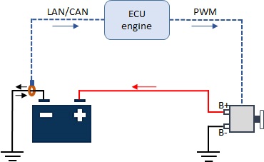
The engine ECU controls the operation of the alternator based on the data obtained from the sensor on the minus terminal of the battery. The sensor on the minus terminal is in the form of a current clamp (Hall sensor) that encompasses the minus cable or the voltage divider (shunt) on the terminal and measures the strength of the charging and discharging current of the battery. It often contains a temperature sensor and can measure the battery temperature. It sends data to the engine ECU via the LIN or CAN network.
Battery current sensors in the form of current clamps or voltage dividers
The ECU engine determines the current state of the power system based on data on the size of the charging and discharging current, the network voltage, and the battery temperature (measured or estimated). It recognizes several modes and regulates the power supply to the rotor windings using PWM. The size of the PWM power supply determines the strength of the magnetic field and the size of the alternator output voltage.
ECU-controlled alternator
When the error light comes on or the operation of the power supply system is suspected, diagnostics are first performed by reading the error codes. If errors are stored, based on the error code and operating instructions, we approach finding the fault. The check can include the alternator, the current sensor, the wires with the connectors, the battery, and finally the ECU engine.
The output voltage from the alternator, battery charge and discharge current, PWM regulation, sensor power, and ECU condition can be checked by measurement. All parameters are monitored via the actual values on the diagnostic device which are visible from the ECU side. In parallel, the same parameters are measured with measuring devices such as an ammeter (current clamp), voltmeter, and oscilloscope recording of PWM signals.
Relationship between PWM regulation and alternator output voltage
Based on the instructions for checking, diagnostics, reading the actual values on the diagnostic device, measuring the current and voltage, and recording the signal, the condition of the power supply system is determined and the malfunction is detected.


")